

Design of the hydraulics for a Kaplan residual water turbine
A mid-sized company commissioned the development of the hydraulics for a Kaplan residual water turbine. Due to the changes in the European Water Framework Directive, the demand for turbines for this kind of applications is increasing. As part of a design study, the nominal data and the main data were determined: maximum flow Qmax = 1.5m³/s, minimum flow Qmin = 0.8m³/s and specific speed nq = 300rpm. The framework conditions were determined by the following parameters: diameter D = 0.65m and a 7-pole generator.
Based on the design for a meridian section a completely new design has been developed. As regulatory concept of the residual water turbine a semi-regulated version with an adjustment of the blade at constant vane position was designed. However, the vanes of the residual water turbine had to be designed in such a way that the guide vane in case of clogging by floating debris can be manually “turned over” the regular blade pitch.
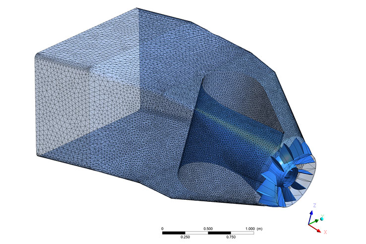
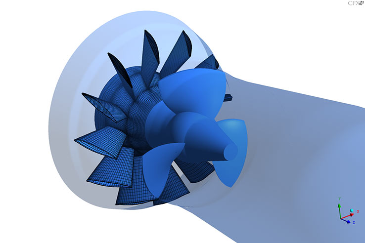
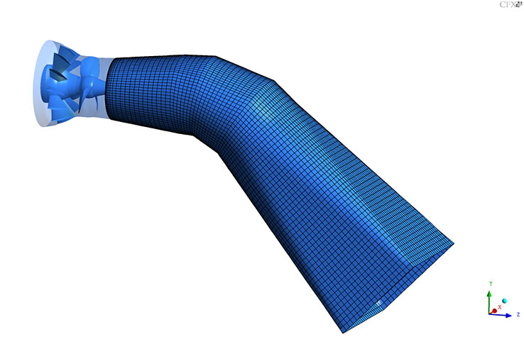
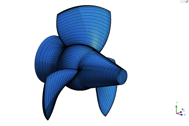
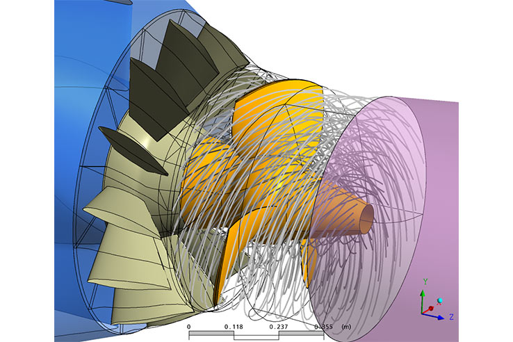
Meshes of the individual components developed by means of CFD
As of the semi-regulation of the Kaplan turbine it is particularly important to develop a blade profile whose leading edge is, to a large extent, resistant to an inflow from the wrong direction. Two different concepts have been applied – the dimensioning of the profile according to Scholz-Czibere and the design of a blade from the NACA 65 series profiles which is popular in water turbine applications although it is normally a standardized profile used for airfoils.
In addition to the efficiency optimisation for every single span a variety of profile thicknesses were simulated as well as various leading edge radii. As outer contour a hemispherical as well as a spherical design has been analysed.
Flow visualisation
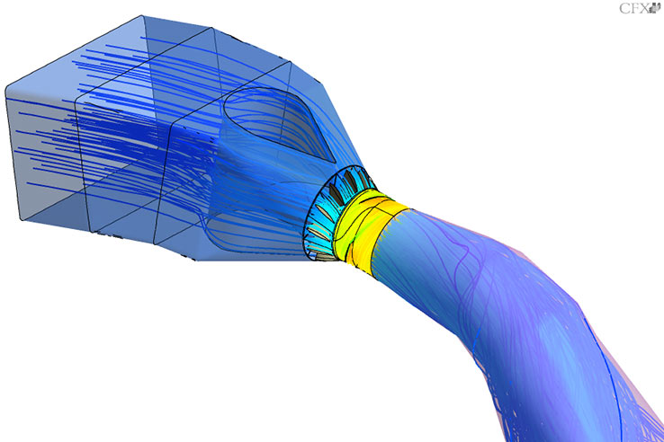
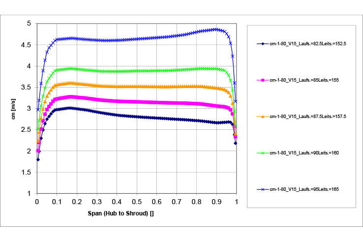
The sigma values reached are far below the theoretically calculated values and illustrate good cavitation behaviour of the blade. Choosing a fixed guide vane position for the hydraulics being operated as semi-regulated residual water turbine has an enormous impact on the efficiency curve shape achieved. The decision whether or not to select a constant guide vane position has to be taken based on the actual flow range. Figure 3 shows the steady flow after the runner by means of an analysis of the meridional flow rate cm at various guide vane positions.
Meridional flow rate after the runner at the design point with various guide vane positions
Core competences
Our services for turbines
- Product development
- Designing
- Optimisation
- Refurbishment
- Troubleshooting
» Details
We do research, development and optimisations for
- Hydraulics for turbines / pump turbines / pumps
- Acceptance tests acc. to IEC standards
- Nozzels
- Spirals
- Turbine in- and outtakes
- Valves & fittings
- Runners, guide vanes
- Water hammer
- Seals
- Surge chamber
- Penstock
- Refurbishment
- Efficiency
- Life cycle
- ...
We solve your challenge. Contact us.