
Pelton turbine: distribution pipeline, wheel / cup geometry
For a medium-sized manufacturer the new construction of a distribution pipeline and the runner cup geometry had to be analysed.

The geometry submitted by the client in the form of a stp-file was revised, debugged and meshed by means of ICEM CFD®. Together with the adjusting rod, the guide plate, the adjusting rod bearing and the nozzle needle, the nozzles were meshed in the position given and/or pre-set by the client. In order to be able to additionally calculate the developing water jet in the air, the flow zone after the nozzle exit was modelled and two-phase CFD calculations (air and water) were realised. The thus generated mesh of a Pelton nozzle consists of 780.000 nodes; the total calculation setup of the distribution pipeline comprises 5.3 million nodes.
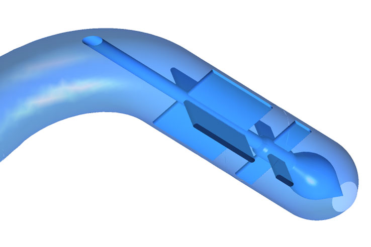
As of the pipeline geometry used the flow is redirected twice. It has to be mentioned that a double flow deviation on one plane is already critical. As soon as the plane changes, however, swirling of the flow increases which has an impact on the jet quality. And that is exactly the situation with the initial design of this distribution pipeline. The following picture shows a streamline plot for the distribution pipeline in which strong sections of low speed, recirculation zones and the above-mentioned swirling of the flow are clearly identifiable. In jet direction the peripheral speed (clockwise is positive) is depicted on several levels. In the inner part of the nozzle the positive and negative rotation zones alternate. As of this, the jet flow has to be characterised as quite “unhealthy” and the flow will in fact burst.

As of a lack of built-in components, the swirl (radius * peripheral speed) generated in flow direction remains on a high level (slightly decreasing tendency), however, this is compensated by the reduction of the nozzle diameter which results in an increase of the peripheral speed.

This speed component is given to the jet at the nozzle exit and can cause deterioration of the interaction between jet and bucket.
The installation of a four-legged component in the area of the rod guide is being proposed whereas a three-legged component would be feasible as well. That way the swirl caused by the double flow deviation could be reduced and the jet quality could be increased to the highest possible level.